SDN Cisco DCNM + iTRACS
Nexus for the data network, MDS for Fibre Channel. The two networks that keep your data center running, now with physical location, real-time status and alarms, all in a single floor plan.
WHAT WE ARE INTEGRATING
Monitoring and transfer of switch metrics
INTEGRATED SYSTEMS
Cisco DCnM + iTRACS DCiM
MAIN OUTCOME
Real data from the entire data center fabric (Nexus for LAN and MDS for Fibre Channel) in the DCIM
Integration context
iTRACS DCiM ON PREMISE
Vendor: iTRACS
Version: iTRACS DCiM según entorno del cliente
Modules: iTRACS CI API REST
Cisco DCNM ON PREMISE
Vendor: Cisco
Version: Cisco DCNM según entorno del cliente
Modules: API REST
Node Red ON PREMISE
Vendor: Node Red
The challenge: why was this integration needed?
- The data center fabric is the quietest and most devastating point of failure. When a core Nexus switch or an MDS Fibre Channel switch goes down, you don’t lose a single network link. You lose connectivity for dozens or hundreds of servers to the network, to storage, or to both. Yet the physical infrastructure team needs to know which rack, which unit and which cabling that switch is on in order to act. Without integration, translating a “DCNM alarm” into a “physical intervention in the data hall” relies on manual documentation that is rarely up to date when a crisis hits.
- SAN (Fibre Channel) visibility missing from the physical inventory. MDS switches manage the storage network: the connection between servers and disk arrays. They live in the data center, but usually only the storage team knows and manages them. The DCIM records servers and storage, but the fabric that connects them (the MDS switches, their ports, their capacity, their status) is a blind spot. Integrating DCNM closes that gap. Every Fibre Channel switch appears in the DCIM with its location, operational status, port capacity and alarms, giving full visibility into a layer that is currently invisible to infrastructure management.
- Fabric port capacity without physical growth context. DCNM knows how many ports on each Nexus and MDS switch are in use and how many are available. But it doesn’t know whether there is room in that rack for another switch, whether the PDU can take more load, or whether the patch panel has free ports. The decision on “where to put the new switch” is made without real physical data. The integration makes it possible to plan fabric growth by combining logical capacity data (DCNM) with physical capacity data (DCIM).
- Two management worlds that don’t talk to each other: data network and storage network in silos. In a data center, the network team manages the Nexus switches in DCNM, the storage team manages the MDS switches (sometimes in a separate DCNM instance or in SAN tools), and the infrastructure team manages physical location in the DCIM. Three teams, three tools, three partial views of the same data center. Integrating DCNM with the DCIM creates, for the first time, a unified view where the entire data center fabric, LAN and SAN, appears on the physical map with real operational data. This is especially valuable in environments with multiple data centers (such as the two sites of the Ministry of Justice), where information becomes even more scattered.
The integration addresses the need to have Cisco DCNM data available in iTRACS DCIM, avoiding manual entry or updating of monitored values.
- Platform integration: connection between Cisco DCNM and iTRACS DCIM through their respective REST APIs.
- Asset synchronization: automatic identification of the same switch in both platforms by IP address, serial number and name.
- Relationship management: a relationship file is maintained so that identified matches can be reused in subsequent runs.
- Log management: logs are generated for the actions performed in each cycle, making it easier to detect and resolve errors.
- Configurable execution frequency: the process runs every 15 minutes by default and can be adapted to each customer’s needs.

The systems in the ecosystem
SYSTEM | DESCRIPTION | PROVIDES | RECEIVES |
Cisco DCNM | Management and monitoring platform for Cisco network infrastructure. | IInformation on monitored switches. | Nothing |
iTRACS | Data center infrastructure management (DCIM) platform. | Storage of the data obtained from the Cisco DCNM platform. | Values obtained from the Cisco DCNM platform. |
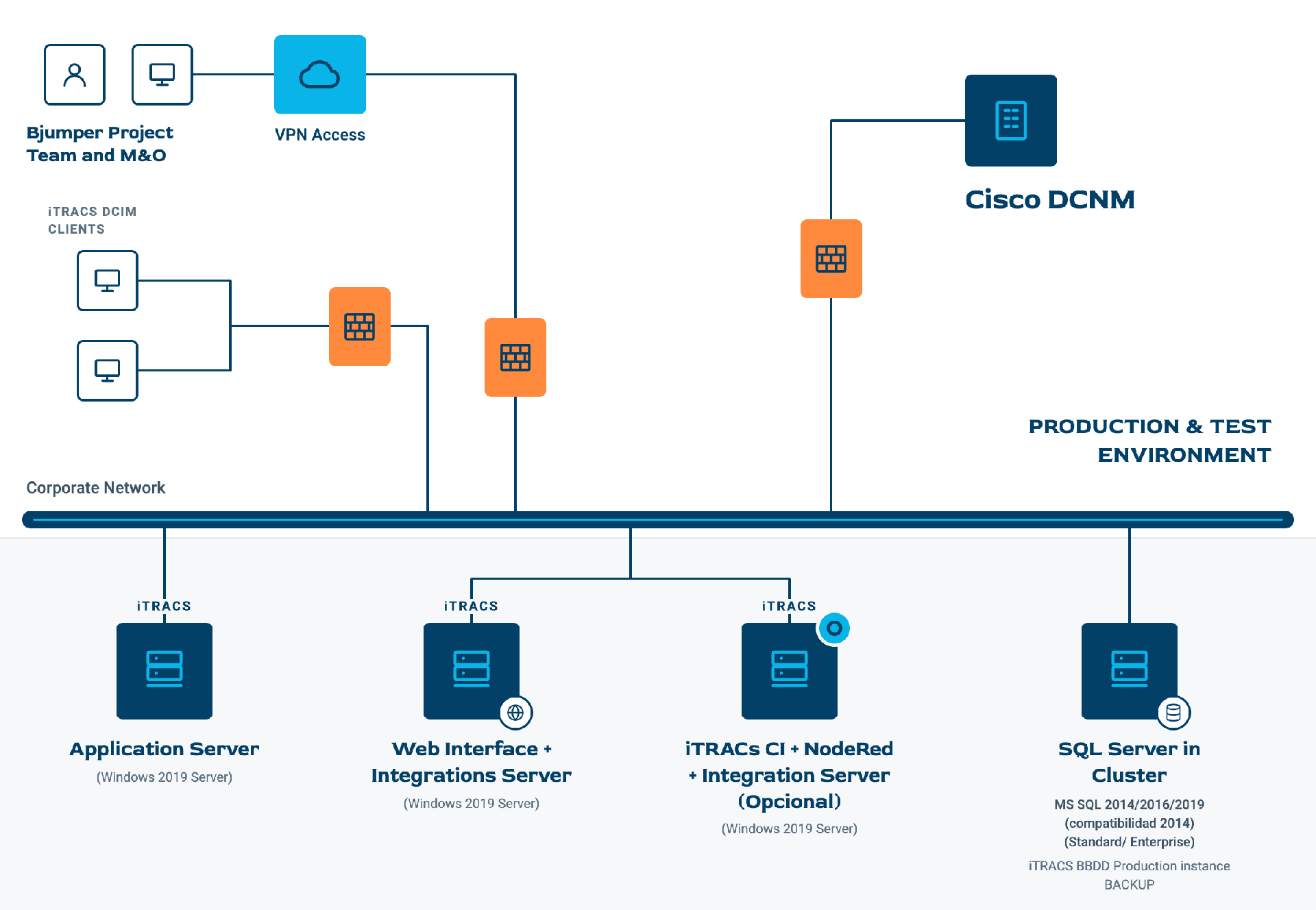
The connection diagram
The architecture consists of two external systems (Cisco DCNM and iTRACS) and an integration server running a Node-RED flow, deployed on a Windows server.
The data flow in action
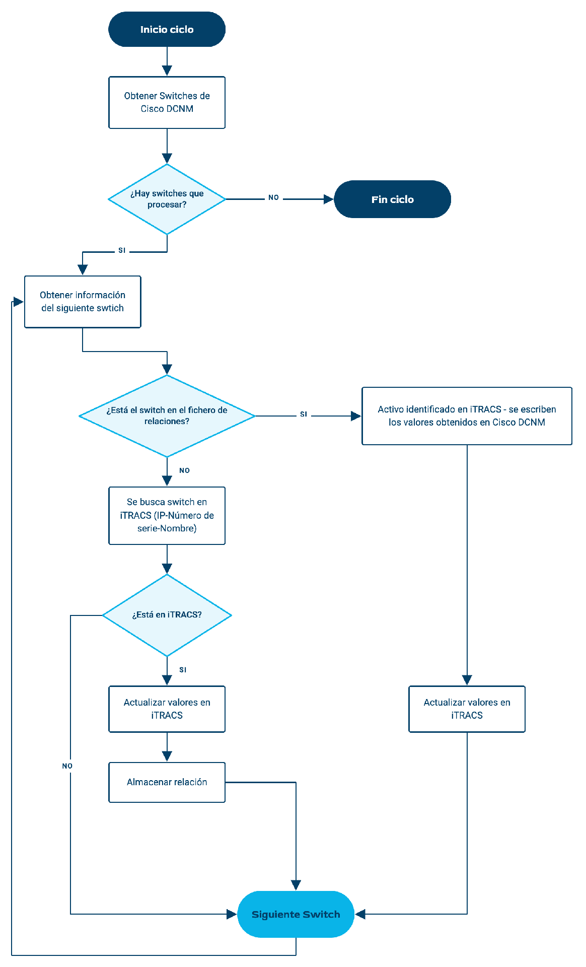
Monitoring flow: from Cisco DCNM to iTRACS DCIM
Cycle start
Node-RED starts a new run of the process at the configured frequency.
The flow queries the Cisco DCNM REST API to retrieve the monitored switches and the available information for each device.
Data selection
From the data retrieved, only the monitored values that are relevant to the project and need to be transferred to iTRACS DCIM are selected.
Asset identification
For each switch retrieved from Cisco DCNM, the flow looks for its equivalent asset in iTRACS DCIM. The search follows this order:
a. IP address.
b. Serial number.
c. Name.
Once the asset is found, the match between both systems is recorded, including the information needed to identify the Cisco DCNM asset and its corresponding asset in iTRACS.
Write to iTRACS
Node-RED uses the iTRACS CI REST API to write the monitored values to the asset’s corresponding datastores.
All operations performed during the cycle are recorded in log files.
Next iteration
In the next run, the relationship file is reused to avoid a full asset search in iTRACS.
VOLUME
Data volume will depend on the number of monitored switches and the values selected for transfer to iTRACS.
FREQUENCY
Periodic execution, configurable for each customer.
Data flow diagram
What made the difference
Design decisions that weren’t the obvious ones, and why we made them.
Clave 2: sistema de log
We built in a logging system that records the operations performed in each cycle and helps identify potential errors.
Key 1: Automatic asset mapping
We designed an automatic mapping mechanism between Cisco DCNM and iTRACS DCiM assets, using a search order based on IP address, serial number and name.
In addition, once a match is found, it is stored in a relationship file, so the full search in iTRACS does not have to be repeated in every cycle.
Let’s talk about your integration
Tell us which systems you have and which ones need to talk to each other.